
Problem
A high-throughput material-handling scenario calls for coordinated equipment sequences, dependable device integration and clear fault information so operations and maintenance teams could respond quickly to interruptions.
Organize the work around equipment ownership and observable state. Define conveyor zones, requests, availability, routing conditions and fault responses so a stopped route can be traced to the device or permission responsible for the stop. This approach supports coordinated development across PLC logic, drives, sensors and operator information without exposing proprietary line architecture.
A proposed commissioning plan progresses from individual devices to zone behaviour and then integrated material flow. Use controlled fault scenarios to check that a failed device, blocked path or interrupted command produces a predictable stop and a useful diagnostic. Check recovery separately from initial operation because the safest response to a fault is incomplete if the system cannot return to service in a controlled way.
Solution
Define the operating states and equipment interfaces before implementing control logic.
Structure alarms and diagnostics around the field condition preventing operation.
Plan checks of manual functions, automatic sequences, faults and recovery during commissioning.
Review the detailed illustrative work package
Engineering scope
- PLC sequence, permissive and interlock development
- Conveyor, sensor, actuator and VFD integration
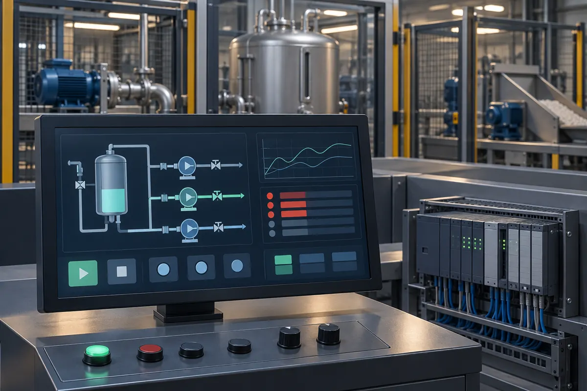
- HMI status, alarm and diagnostic functions
- Commissioning support, documentation and operator handover
Coordinated sequencing · Controls work scope
Platforms and equipment interfaces
- PLC / HMI
- Conveyors & sortation
- VFDs
- Industrial I/O
Operating constraints
- Multiple conveyor zones and devices need to coordinate without hiding the exact reason a route cannot advance.
- Operational continuity requires controlled testing and clear recovery rather than broad trial-and-error changes.
- Maintenance needs diagnostics that connect an HMI message to a field condition and equipment location.
Interfaces
- Conveyor and sortation drives via VFD control and status
- Photoeyes, encoders and presence sensors for tracking and accumulation
- PLC-to-PLC and device-network communication across zones
- HMI status, alarm and diagnostic screens for operations and maintenance
Proposed engineering decisions
Organize control logic around conveyor zones and explicit permissives rather than one monolithic sequence.
A stopped route can be traced to the specific device or permission responsible, which helps focus fault-finding and keeps the logic maintainable as the system changes.
Structure alarms around the field condition preventing operation, not around generic controller faults.
An HMI message points to a device and location, so maintenance starts at the cause instead of interpreting a broad fault code.
Verify controlled recovery separately from initial operation.
A safe stop is only half the requirement; the system also has to return to service predictably after a blocked path or failed device.
Verification approach
- Check device feedback, motor direction, sensor response and VFD control one zone at a time.
- Exercise route requests, accumulation, permissives, blocked conditions and controlled restart behaviour.
- Review alarms against actual field causes and record the as-left controller and HMI versions.
Handover requirements
- Prepare maintainable sequencing and status information organized around equipment states.
- Capture accepted changes, backups and commissioning findings for operations and maintenance follow-up.
- Keep project identity and proprietary layouts outside the public case study.
Result and evidence limits
The intended deliverable is maintainable material-handling sequencing and practical fault visibility; acceptance requires equipment-specific test evidence.
- The highlighted label describes the illustrative controls work scope, not a measured production gain or service-population figure.
- This is an engineering walkthrough, not evidence of a completed customer project. Agree scope and acceptance evidence for the customer’s own equipment and operating context.
- Client identities, proprietary layouts and confidential operating records are not published.
This engineering walkthrough illustrates a proposed method, not a verified completed-project outcome. Numerical performance and operating-scale claims are not published here until their supporting records, original context and publication permission have been reviewed. Acceptance evidence is required for each actual installation.
Earlier employment and retained technical material are not presented as AranVision contracts. Customer identities and confidential records are withheld.
Have a related operating challenge?
Share the system, problem and next decision.
Discuss your projectNo account needed for an initial enquiry. Do not include passwords or confidential files.