Optional Google Analytics and Google Ads measurement use advertising identifiers to measure site use and successful enquiries. Enquiry details are not included; personalized ads and enhanced conversions stay off. You can reject cookies and still enquire. Read our privacy notice.
One coordinated package. Drawings, layout and BOM.
EPLAN electrical CAD drafting and control-panel documentation for OEMs, panel builders and industrial facilities in Toronto, the GTA and Ontario. Remote drafting support is available by arrangement for new machines, retrofits and as-built drawing updates.
Electric P8 · Pro PanelSoftware platforms used for the agreed work package.
Image: EPLAN · manufacturer software illustration
EPLAN Electric P8
Intelligent schematics, not isolated drawing lines.
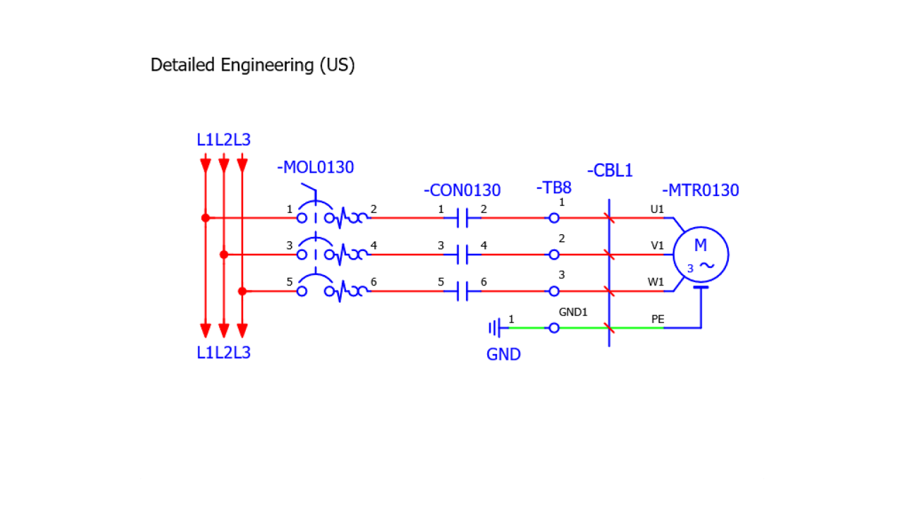
Connect symbols to device, cable and connection data. Numbering, cross-references and reusable templates help maintain a consistent drawing package as the design develops.
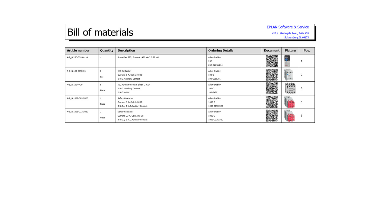
Derive parts and wire lists from the project. Our agreed documentation scope can include BOM review, terminal plans, cable schedules and PLC connection records.
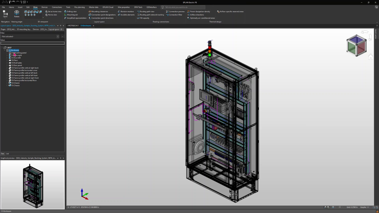
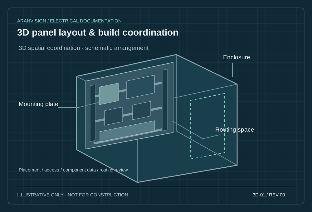
Arrange the enclosure, mounting plate, rails, ducts and devices in 3D. Review space and routing; agree any wire-length, drilling, cut-out or manufacturing exports with the panel builder.
Data Portal supplies device information, schematic macros, 2D/3D graphics and document links. These records can support parts management, schematic development and cabinet layout.
We confirm the required model and revision, available component data and client standards. A portal record does not establish stock, suitability, approval or the exact device installed on site. Access, software version and required modules are confirmed for each work package.
AranVision service scope
Choose a complete package or a defined drawing task.
Electrical CAD design & drafting
Power and control schematics, single-line drawings, PLC interfaces and consistent device identification.
Mounting-plate and door arrangements, device placement, service access and enclosure coordination.
BOM & device-data review
Manufacturer, complete part number, quantity, accessories and document references tied to the drawing revision.
As-built drawings & revision updates
Project structure, title blocks, agreed macros, drawing conventions, field redlines and controlled revision records.
Panel-builder handover
Review PDFs, agreed editable projects and checked reports; manufacturing data only in the confirmed scope and format.
View illustrative documentation concepts
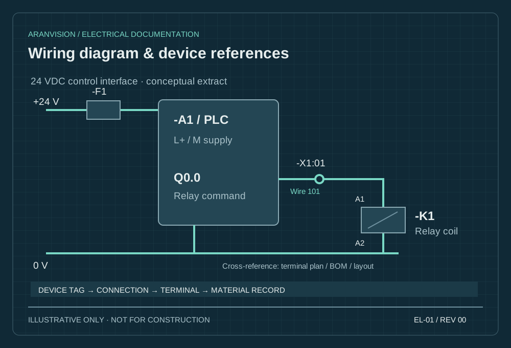
These simplified AranVision illustrations explain the relationship between drawings, layout and material records. They are not EPLAN application screenshots or construction documents.
Illustrative example · not an EPLAN application screenshot or a customer project01
Electrical schematics & wiring diagrams
Power and control circuits, device tags, wire numbering, terminal plans, cable schedules and PLC I/O references.
Illustrative example · not an EPLAN application screenshot or a customer project02
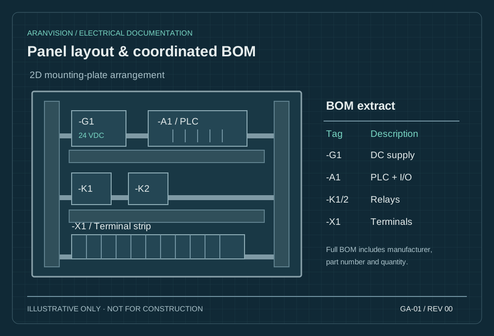
2D panel layout & enclosure coordination
Mounting-plate arrangement, DIN rails, cable ducts, device placement, door layout and service-access review.
Illustrative example · not an EPLAN application screenshot or a customer project03
3D panel layout & build coordination
EPLAN Pro Panel work packages for spatial coordination, component placement and routing preparation, with model data and required modules agreed at kickoff.
Beyond the drawing sheet
Bill of materials, reports & handover
Connect the device shown on a drawing to its location, terminal reference and material record. Changes should remain traceable across the package.
Bill of materials (BOM) — manufacturer, full part number, description, quantity and revision basis; availability and substitutions require separate confirmation.
Connection documentation — terminal strips, cable and wire lists, PLC I/O schedules and cross-references.
Controlled drawing updates — existing drawings, field redlines, revision records and as-built updates against verified field information.
Agreed delivery formats — review PDFs, editable project files and agreed reports/exports, with software version and client standards confirmed before work starts.
From brief to handover
A reviewable workflow, with clear release points.
01 · Define
Agree the system boundary, client standards, source drawings, EPLAN version and required deliverables.
02 · Develop
Coordinate device tags, schematics, layout and material records; log assumptions and missing information.
03 · Review
Resolve drawing comments with the client and panel builder. Check interfaces and report consistency before release.
04 · Hand over
Release the agreed revision and formats, with open items and a controlled route for verified as-built updates.
Start with the package you need.
Send the panel or machine purpose, drawing status, preferred EPLAN version and required outputs. We confirm inputs, responsibilities, review stages and scope before quoting.
EPLAN is a trademark of its respective owner. AranVision is an independent service provider; displaying the software brand does not claim EPLAN partnership, certification or endorsement. Regulated engineering and approvals follow the responsibility boundary stated below.
Delivery approach
Work that can be reviewed, tested and handed over.
A strong drawing package connects control intent to fabrication, wiring, checkout and maintenance. AranVision develops coordinated electrical documentation with practical attention to interfaces, protection, serviceability and revision control.
EPLAN Electric P8EPLAN Pro PanelAutoCAD ElectricalSolidWorks Electrical2D / 3D panel layoutsBill of materials
Scope clarity
What a useful work package needs to establish.
The drawing package is treated as one coordinated dataset rather than a collection of independent sheets. Device identifiers, wire numbers, terminal assignments, PLC addresses and bill-of-material entries are checked across the package. Power, control, safety and communications are separated clearly enough for fabrication, inspection and field troubleshooting.
Component selection and layout review consider the available fault information, protection approach, conductor and terminal needs, grounding and bonding, heat, environmental conditions, service access and field wiring. Final authority, certification and inspection responsibilities remain defined by the project jurisdiction and contracting structure.
Every engagement begins with a written boundary for access, production impact, client-supplied information, approvals and third-party responsibilities. Recommendations are tied to the evidence available at the time. If field discovery changes a critical assumption, the effect on scope, testing and acceptance is reviewed before the work proceeds.
Project readiness
Fit, inputs and acceptance before work starts.
These checkpoints keep responsibilities visible and prevent important interfaces from becoming late-stage surprises.
01
Best-fit assignments
A new or retrofit controls package that needs implementation-ready electrical documentation
An OEM or panel shop that needs EPLAN, SolidWorks Electrical or AutoCAD documentation and design support
An installed panel requiring controlled redlines, normalization or as-built documentation
02
Inputs to provide
Supply characteristics, loads, architecture, I/O, enclosure environment and interfaces
Client drafting rules, preferred components, applicable codes and approval path
Existing drawings, field redlines, short-circuit information and panel-shop responsibilities
03
Acceptance evidence
Cross-checked schematics, I/O, terminals, cables, BOM and panel layout
Recorded design assumptions, exclusions and review comments
Released revision plus controlled redline and as-built workflow
Project outcomes
What the engagement is designed to improve.
Consistent device, wire and terminal references
Clear separation of power, control and communications
Coordinated I/O, BOM and panel-layout information
Fewer questions during panel build and field checkout
Scope boundary
Programming, controls documentation, integration, testing and commissioning support are delivered within the agreed responsibility matrix. Any regulated professional engineering, electrical contracting, panel certification or authority approval is identified separately and assigned to the appropriately licensed or authorized party.
Typical deliverables
A defined package with clear technical outputs.
The final scope is adjusted to the installed system, project stage, client standards and site responsibilities.
01
EPLAN electrical schematics, wiring diagrams and single-line diagrams
02
2D panel layouts, 3D layout support and enclosure coordination
03
I/O, terminal and cable documentation
04
Coordinated bill of materials with manufacturer and full part number
05
Power-distribution and protection review inputs
06
Redlines and as-built drawing updates
Delivery method
Three decisions that keep controls work under control.
01
Confirm requirements
Review supply, loads, control architecture, interfaces, environment, applicable standards and client documentation rules.
02
Coordinate the package
Align schematics, I/O, terminals, cables, BOM and panel layout so each deliverable tells the same story.
03
Review for buildability
Check clearances, service access, separation, field wiring and test points before release.
Common questions
Questions to settle before kickoff.
Can you work from existing drawings and field redlines?+
Yes. Existing packages can be reviewed, normalized and updated into a controlled drawing set for retrofit or as-built use.
What is the difference between Electric P8 and Pro Panel?+
Electric P8 supports electrical schematics and project reports. Pro Panel adds three-dimensional cabinet layout and related routing and manufacturing data. We confirm the necessary version, modules and component data before agreeing the deliverables.
Can we request only drawings, a BOM or a panel-layout update?+
Yes. A defined task can cover an electrical drawing set, connection schedules, a BOM review, a 2D layout or a 3D coordination package. We establish the source information and review boundary so a partial assignment does not imply approval of the entire installation.
What should we provide for an EPLAN quotation?+
Describe the machine or panel, the current drawing status, preferred software version, required outputs and target date. Existing drawings, component lists, I/O schedules, client templates and non-confidential reference images help define the work. Final file exchange and any confidential project records use the agreed private channel.
Do you manufacture panels?+
AranVision focuses on controls documentation and design support and can coordinate defined review and commissioning packages with a client-selected panel shop or licensed electrical contractor. Fabrication, certification and installation responsibilities are identified in the project scope.
Next step
Send the system type, current issue, location and target date.

 Electric P8 · Pro Panel